
Daikin Altherma A/B Series
Introduction to the Original Daikin Altherma
The original Daikin Altherma, launched in 2006, was one of the very first mainstream air-to-water heat pumps designed specifically for European homes. It marked a major shift away from traditional fossil-fuel heating by offering a highly efficient, electrically driven alternative capable of delivering reliable heating, cooling, and domestic hot water.
The first-generation Altherma system introduced several features that set new standards at the time:
Air-to-water technology based on their existing air conditioning range.
Low-temperature versions in split and monobloc variations.
High-temperature versions in split format able to reach up to 80°C by utilising 2 compressors in cascade format. One in the outdoor unit and a separate R134a refrigerant circuit in the indoor unit to achieve the additional temperature.
R410A refrigerant which was an innovation at the time.
The original Altherma became the foundation for all later Daikin heat pumps, eventually evolving into the highly efficient Altherma ‘C Series’ and today’s advanced Altherma 3 and 4 ranges.
If you have this heat pump…
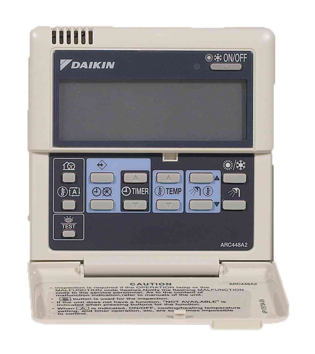
You will be familiar with the difficult to use controller.
This early range of heat pumps were derived from Daikin’s commercial ‘Sky Air’ air conditioning range, with factory modifications to heat water in a plate heat exchanger instead of an air conditioning indoor unit.
The air conditioning controller was reprogrammed for the air to water heat pump configuration and a new sticker installed for the new buttons configurations. This controller was not designed to be used as a heat pump controller and so is quite difficult to use.
Although the controller could be used as a room thermostat, most installations used 3rd party thermostats however the hot water controls must be via the Altherma controller.
How to set the clock


How to set & boost the hot water


Fault Codes / Error Codes Lookup
The red light flashes and the display indicates a fault code. Search for your code below.
Scroll down for the High Temperature System error codes.
🟢 Low – basic checks a homeowner can safely try. 🟠 Medium – some checks possible, engineer recommended if it persists. 🔴 High – switch off if in doubt and contact an engineer.
80 – Inlet water temperature thermistor failure
Cause: Inlet water temperature thermistor is broken.
What you can do: No homeowner serviceable parts.
Action: 🔴 Contact your local dealer / service engineer.
81 – Outlet water temperature thermistor failure
Cause: Outlet water temperature thermistor is broken.
What you can do: No homeowner serviceable parts.
Action: 🔴 Contact your local dealer / service engineer.
89 – Water heat exchanger freeze-up
Cause: Heat exchanger freezing due to either low water flow or refrigerant shortage.
What you can check:
- If low flow is suspected, follow the checks for code
7H.
Action:
• If low flow: follow 7H checks.
• If refrigerant shortage suspected: 🟠 Contact your local dealer.
7H – Flow failure (water flow too low / no flow)
Cause: Minimum required water flow (12 l/min) is not reached.
What you can check:
- Confirm all water circuit shut-off valves are fully open.
- Clean the system water filter if accessible.
- Purge air from the system (bleed radiators / high points).
- Check water pressure – should be > 1 bar when cold.
- If you can access pump controls, set to highest speed.
- Check for obvious leaks or pressure loss.
Advanced checks (installer):
- Verify system is within operating range.
- Confirm expansion vessel and pump sizing are correct.
- If error occurs during defrost: check backup heater supply/fuses and DHW tank thermostat (≥ 50 °C on EKHWSU).
Action: 🟠 If the fault persists after these checks, contact your installer or Daikin engineer.
8H – Outlet water temperature too high (>65 °C)
Cause: Outlet water temperature from the indoor unit is excessively high.
What you can check:
- Ensure heating setpoints are reasonable (not set extremely high).
Installer checks:
- Check backup heater contactor is not short-circuited.
- Check outlet water thermistor reading is correct.
Action: 🟠 If the error repeats, contact your installer / engineer.
A1 – Indoor unit PCB defective
Cause: Failure of the indoor unit control PCB.
Action: 🔴 Switch the unit off if behaviour is abnormal and contact your local dealer.
A5 – Refrigerant temperature too low / too high (R13T)
Cause: Refrigerant temperature outside safe range during cooling or heating.
What you can do: No safe homeowner adjustments.
Action: 🔴 Contact your local dealer / F-Gas engineer.
AA – Backup heater thermal protector open
Cause: Backup heater has overheated and its thermal protector has opened.
What you can check / do:
- Reset the backup heater thermal protector using the reset button (location in manual).
If the error persists: The backup heater thermal fuse may be blown.
Action: 🟠 Contact your local dealer if the code returns after reset.
AC – Booster or secondary DHW heater thermal protector open
Cause: Thermal protector of the booster heater or secondary protector in EKHWSU DHW tank has opened.
What you can do: Reset the affected thermal protector (per installation manual).
Action: 🟠 If it trips again, contact your installer to investigate cause of overheating.
C0 – Flow switch failure (closed when pump stopped)
Cause: Flow switch remains closed despite the pump being stopped, usually due to dirt or sticking.
What you can check:
- Ask an installer to check and clean the flow switch if necessary.
Action: 🟠 Contact your installer if the problem persists.
C4 – Heat exchanger thermistor failure
Cause: Heat exchanger temperature sensor is broken.
Action: 🔴 Contact your local dealer / engineer for sensor replacement.
E1 – Outdoor unit PCB defective
Cause: Failure of the outdoor unit control PCB.
Action: 🔴 Contact your local dealer. Do not attempt electrical work yourself.
E3 – Abnormal high pressure
Cause: Refrigerant circuit pressure too high (e.g. blockage, fan/coil issues).
Checks: Installer verifies unit is operating within its specified range.
Action: 🔴 Contact your local dealer / engineer.
E4 – Low pressure sensor actuation
Cause: Refrigerant circuit pressure too low (possible leak or charge problem).
Action: 🔴 Contact your local dealer / F-Gas engineer.
E5 – Compressor overload activation
Cause: Compressor overloaded, often due to abnormal conditions in the refrigerant or water circuit.
Action: 🔴 Switch off if unusual noises are present and contact your local dealer.
E7 – Fan lock failure (fan locked)
Cause: Outdoor fan is obstructed or fan motor has failed.
What you can check:
- Visually check (from outside the grille) for debris, ice or objects blocking the fan.
Action: 🟠 If no obstruction or if the error returns, contact your local dealer.
E9 – Electronic expansion valve malfunction
Cause: Problem with the electronic expansion valve operation.
Action: 🔴 Contact your local dealer / F-Gas engineer.
EC – Domestic hot water temperature too high (>89 °C)
Cause: DHW temperature has exceeded safe level.
Checks:
- Installer checks booster heater contactor is not short-circuited.
- Check DHW thermistor reading.
Action: 🟠 Turn off hot water if you are concerned and contact your installer.
F3 – High discharge temperature (often coil blockage)
Cause: Discharge temperature too high, commonly from outdoor coil blockage.
What you can check:
- Visually check and clean the outdoor coil / grille (dust, leaves, snow, etc.).
Action: 🟠 If the coil is clean and error persists, contact your dealer.
H3 – Malfunctioning HPS system
Cause: Internal protection system malfunction.
Action: 🔴 Contact your local dealer.
H9 – Outdoor temperature thermistor failure
Cause: Outdoor temperature sensor is broken.
Action: 🔴 Contact your local dealer.
HC – DHW tank thermistor failure
Cause: Domestic hot water tank sensor failure.
Action: 🔴 Contact your local dealer.
J1 – Pressure sensor malfunction
Cause: Pressure sensor fault.
Action: 🔴 Contact your local dealer.
J3 – Discharge pipe thermistor failure
Cause: Discharge pipe sensor failure.
Action: 🔴 Contact your local dealer.
J5 – Suction pipe thermistor failure (outdoor)
Cause: Suction pipe sensor failure.
Action: 🔴 Contact your local dealer.
J6 – Aircoil thermistor frost detection failure
Cause: Frost detection sensor fault on aircoil.
Action: 🔴 Contact your local dealer.
J7 – Aircoil thermistor mean temperature failure
Cause: Mean aircoil temperature sensor failure.
Action: 🔴 Contact your local dealer.
J8 – Liquid pipe thermistor failure (outdoor)
Cause: Liquid pipe sensor failure.
Action: 🔴 Contact your local dealer.
L4, L5, L8, L9, LC – Electric component failures
Cause: Generic electrical component failures inside the unit.
Action: 🔴 Switch off if in doubt and contact your local dealer.
P1 – PCB failure
Cause: Printed circuit board failure.
Action: 🔴 Contact your local dealer.
P4 – Electric component failure
Cause: Internal electrical component fault.
Action: 🔴 Contact your local dealer.
PJ – Failure of capacity setting
Cause: Incorrect or failed capacity setting on the unit.
Action: 🔴 Contact your installer / Daikin engineer.
U0 – Refrigerant failure (possible leak)
Cause: Refrigerant shortage/leak or charge issue.
Action: 🔴 Contact an F-Gas certified engineer. Switch off if you suspect damage.
U2 – Main circuit voltage failure
Cause: Supply voltage outside acceptable range or electrical supply issue.
Action: 🔴 Contact your installer or qualified electrician / dealer.
U4, U5, U7, UA – Communication failures
Cause: Communication error between indoor/outdoor units or controllers.
What you can try:
- Power cycle the system fully off for 5–10 minutes, then back on.
Action: 🟠 If errors return, contact your installer to check wiring and PCBs.
Split High Temperature Error Codes
Error codes for the ERSQ-AAV1, ERRQ-AAV1, EKHBRD-AA, EKHBRD-AB, EKHBRD-AC, EKHBRD-AD, EKHBRD-AE, R-410A, R134a, EKHTS(U)-A/AB/AC, EKBUHAA6.
🟢 Low – configuration / controls issues. 🟠 Medium – water-side or sensor issues. Engineer recommended if it persists. 🔴 High – electrical / refrigerant faults. Switch off if in doubt and contact an engineer.
A1 – Indoor PCB / EEPROM defect
Cause: Fault reported on the indoor PCB or its E²PROM memory.
Action: 🔴 Try a full power cycle once. If A1 returns, the PCB needs replacing – contact your installer or Daikin engineer.
A6 – Pump error / water system problem
Cause: Circulating pump not turning correctly or water-side problem (blocked flow, air, low pressure).
What you can check:
- All isolation valves in the heating circuit are fully open.
- System pressure is within the normal range when cold.
- Bleed radiators / high points to remove air.
- Clean any accessible strainers/filters.
Action: 🟠 If the code comes back, the pump or system design needs checking by your installer.
A9 – Indoor electronic expansion valve fault (Y1E)
Cause: Moving part (stepper) of the R-410A expansion valve not responding correctly.
Action: 🟠 Engineer job – valve, wiring or PCB must be checked.
AJ – Capacity setting / adapter error
Cause: The indoor PCB does not recognise a valid capacity setting (wrong or missing adapter, or wrong PCB type).
Action: 🟢 Installer needs to confirm the correct capacity plug and PCB part number.
C1 – Communication fault: indoor PCB ↔ fan/control PCB
Cause: Internal comms error between main indoor board and the control/fan board.
Action: 🟠 Usually requires an engineer to check harnesses and PCBs.
C4 – Liquid line thermistor fault (R3T – R-410A)
Cause: Liquid pipe temperature sensor is disconnected, shorted or failed.
Action: 🟠 Engineer to test/replace the thermistor and check the wiring back to the indoor PCB.
C5 – Tank thermistor fault (R2T – DHW)
Cause: Hot water tank sensor is open/short or reading outside its normal range.
Action: 🟠 Installer to check DHW sensor, wiring and tank option setting.
C9 – Return water thermistor fault (R4T)
Cause: Return water temperature sensor is faulty or disconnected.
Action: 🟠 Engineer to check/replace the sensor; system will not control flow temps correctly until fixed.
CA – Leaving water thermistor fault (R5T)
Cause: Flow/“leaving water” sensor fault or wiring issue.
Action: 🟠 Needs testing with a multimeter and replacement if necessary – installer job.
CJ – Room thermostat sensor in controller
Cause: Temperature sensor inside the wall controller is faulty.
Action: 🟢 Try a power cycle; if CJ returns, the controller itself usually needs replacing.
E1 – PCB defect (indoor or outdoor)
Cause: E²PROM/board failure reported on compressor or main PCB.
Action: 🔴 Engineer to diagnose and replace the faulty PCB.
E3 – High-pressure switch triggered
Cause: Refrigerant pressure has exceeded safe limits and the HP switch has opened.
Action: 🔴 Turn the system off and contact an F-Gas engineer – can be due to blocked coil, closed valves, or charge issues.
E4 – Low-pressure sensor actuation
Cause: Suction pressure has dropped too low – often leak, restriction or closed valves.
Action: 🔴 Call an F-Gas engineer; they’ll check charge, valves and low-pressure sensor.
E5 – Compressor motor lock
Cause: Inverter sees the compressor as locked (mechanical or electrical) and stops.
Action: 🔴 Switch off if there are unusual noises; compressor and inverter need professional diagnosis.
E6 – Standard compressor lock / over-current
Cause: Over-current or lock detected on the standard compressor circuit.
Action: 🔴 Do not repeatedly reset; contact an engineer to check compressor, wiring and inverter.
E7 – Outdoor fan motor fault
Cause: Outdoor fan failed to start or run at commanded speed.
What you can check:
- Look for debris, ice or obstructions behind the grille.
Action: 🟠 If clear or if the error returns, fan motor / PCB need testing by an engineer.
E9 – Electronic expansion valve fault (Y1E / Y3E)
Cause: Moving parts of the EEV not behaving correctly or coil/wiring issue.
Action: 🟠 Engineer to check coil resistances, wiring and possibly replace the valve insert.
F3 – Abnormal discharge pipe temperature
Cause: Compressor discharge temperature very high or rising too fast (sensor or refrigerant issue).
Action: 🟠 Have an engineer check the discharge sensor, refrigerant charge and operation.
H9 – Outdoor air thermistor fault (R1T)
Cause: Ambient sensor on the outdoor unit is shorted, open or disconnected.
Action: 🟠 Engineer to replace/rewire sensor; inaccurate readings will affect control and defrost.
J2 – Current sensor malfunction
Cause: Inverter cannot read current correctly (sensor or PCB problem).
Action: 🔴 Needs an engineer to test current sensor and inverter electronics.
J3 – Discharge pipe thermistor fault (R2T / R6T)
Cause: Discharge temperature sensor on indoor or outdoor side is open/short or mis-wired.
Action: 🟠 Engineer to confirm with resistance checks and replace sensor if needed.
J5 – Suction / liquid thermistor fault
Cause: Fault on suction pipe sensors (R3T/R5T) or R-134a liquid sensor (R7T), depending on which unit raises it.
Action: 🟠 Engineer to check correct sensor, wiring and replace if readings are off.
J6 – Heat exchanger thermistor fault (R6T)
Cause: Coil/heat-exchanger sensor open/short.
Action: 🟠 Sensor and harness need checking by an engineer.
J7 – Liquid pipe thermistor fault (R7T – outdoor)
Cause: Outdoor liquid line sensor failure.
Action: 🟠 Engineer to test/replace.
J9 – Subcooling heat exchanger gas sensor fault (R4T)
Cause: Sensor on subcool heat-exchanger gas pipe is faulty or disconnected.
Action: 🟠 Needs sensor and wiring checks by an engineer.
JA – High-pressure sensor fault
Cause: High-pressure transducer reading is invalid (short/open or wired incorrectly).
Action: 🔴 Engineer to compare pressure vs voltage and replace sensor or PCB as needed.
JC – Low-pressure sensor fault
Cause: Low-pressure sensor open/short or wrong sensor connected.
Action: 🔴 F-Gas engineer to verify sensor, wiring and board readings.
L1 – Inverter PCB / power stage fault
Cause: Over-current, IGBT or current-sensor failure on the inverter board.
Action: 🔴 PCB and compressor current need checking by a qualified engineer; PCB replacement is common.
L4 – Inverter heatsink temperature too high
Cause: Inverter radiator fin temperature too high or its thermistor faulty.
What you can check:
- Outdoor air inlets/outlets not blocked.
- Unit not choked with leaves or dirt.
Action: 🔴 If airflow is OK, engineer must check fin sensor, thermal paste and inverter PCB.
L5 – Inverter compressor abnormal
Cause: Excess current in power transistors – possible compressor fault, wiring defect or inverter issue.
Action: 🔴 Engineer to check compressor windings, insulation and inverter stage.
L8 – Inverter current abnormal / overload
Cause: Over-current detected; could be compressor overload or inverter problem.
Action: 🔴 Professional check of compressor load, refrigerant circuit and inverter PCB.
L9 – Inverter start-up error
Cause: Overload detected during compressor start (pressure difference, compressor or inverter fault).
Action: 🔴 Engineer to check start conditions, pressures and compressor/inverter.
LC – Communication fault: inverter ↔ control PCB
Cause: Internal comms error between inverter board and main control board.
Action: 🔴 Engineer should inspect harnesses and likely replace one of the boards.
P1 – High voltage on main inverter capacitor
Cause: Supply imbalance, open phase or capacitor problem detected via DC bus voltage.
Action: 🔴 Electrician/engineer to check 3-phase supply quality and inverter board.
PJ – Faulty PCB combination / wrong inverter type
Cause: Incompatible PCB types detected on the indoor inverter/control combination.
Action: 🔴 Installer must fit the correct replacement PCB for this model.
U0 – Low pressure drop / suspected refrigerant shortage
Cause: Control logic thinks there is not enough refrigerant flow – often due to leak, blockage or faulty low-pressure sensing/EEV.
Action: 🔴 Contact an F-Gas engineer to leak-test and check sensors and expansion valves.
U2 – Power supply insufficient or instantaneous failure
Cause: Mains voltage outside permitted range or severe dips/spikes detected at the inverter.
Action: 🔴 Electrician/installer should check supply voltage, phase balance and inverter PCB.
U4 – Communication fault: indoor ↔ outdoor
Cause: F1/F2 comms wiring problem, outdoor power off, or PCB issue.
What you can try:
- Turn power to the whole system off for 5–10 minutes, then back on.
Action: 🔴 If U4 returns, wiring and boards must be checked by an installer.
U5 – Communication fault: remote controller ↔ indoor
Cause: Loss of communication between controller(s) and indoor PCB, or incorrect MAIN/SUB settings with two controllers.
What you can check:
- Room controller cable firmly plugged in at both ends.
- If two controllers fitted, one set to MAIN and one to SUB.
Action: 🟠 If still present, installer should check cabling, noise issues and the controller PCB.
U7 – Outdoor communication / cool-heat selection issue
Cause: Fault in outdoor side communication or COOL/HEAT selection/addresses.
Action: 🔴 Installer to check mode selector settings and wiring to any outdoor control adapters.
U8 – Communication fault between main and sub controllers
Cause: Wiring or addressing problem between two room controllers.
Action: 🟢 Installer to confirm one controller is MAIN, the other SUB, and cabling is correct.
UA – Communication error indoor ↔ outdoor / combination issue
Cause: Wrong indoor–outdoor combination, over-connected units or outdoor PCB not initialised after replacement.
Action: 🔴 Installer to check model matching, maximum connections and re-run outdoor PCB setup.
UF – System not set yet (wiring / QA issue)
Cause: System wiring or addressing check has failed; QA or indoor–outdoor comms wiring incorrect.
Action: 🟢 Installer must correct wiring and run the system-setting / wiring-check procedure again.
UH – System fault – refrigerant address undefined
Cause: Addressing/connection problem between units – system cannot assign a refrigerant circuit.
Action: 🔴 Installer to check wiring vs piping, addresses and outdoor adapters, then re-initialise the system.
| Error code | Failure cause | Corrective action |
|---|---|---|
| 80 | Inlet water temperature thermistor failure (broken) | Contact your local dealer. |
| 81 | Outlet water temperature thermistor failure (broken) | Contact your local dealer. |
| 89 |
Water heat exchanger freeze-up (low flow) OR Water heat exchanger freeze-up (refrigerant shortage) |
• If low flow: Refer to error code 7H for flow checks. • If refrigerant shortage: Contact your local dealer. |
| 7H | Flow failure (too low or no water flow — min. 12 l/min) |
• Check all shut-off valves are open. • Clean the water filter. • Ensure system is in its operating range. • Purge air from the system. • Verify water pressure (>1 bar when cold). • Set pump to highest speed. • Ensure expansion vessel is OK. • Check water circuit resistance. • If during defrost: check backup heater supply & fuses. • With EKHWSU tank: check thermostat setting ≥50 °C. |
| 8H | Indoor unit outlet water temperature too high (>65 °C) |
• Check backup heater contactor is not short-circuited. • Check outlet thermistor readout. |
| A1 | Indoor unit PCB defective | Contact your local dealer. |
| A5 | Too low (cooling) or too high (heating) refrigerant temperature (R13T sensor) | Contact your local dealer. |
| AA | Backup heater thermal protector is open |
• Press the thermal protector reset button (see manual page 6). • If error persists after reset: backup heater thermal fuse may be blown — contact local dealer. |
| AC |
Booster heater thermal protector open (with DHW tank) OR Secondary thermal protector open (EKHWSU tank) |
Reset the thermal protector. |
| C0 | Flow switch failure (flow switch remains closed while pump is stopped) | Check if flow switch is clogged with dirt. |
| C4 | Heat exchanger thermistor failure (broken) | Contact your local dealer. |
| E1 | Outdoor unit PCB defective | Contact your local dealer. |
| E3 | Abnormally high pressure |
• Check system is within operating range (spec page 47). • Contact your local dealer. |
| E4 | Low pressure sensor actuation |
• Check system is within operating range (spec page 47). • Contact your local dealer. |
| E5 | Compressor overload activation |
• Check system is within operating range (spec page 47). • Contact your local dealer. |
| E7 | Fan lock failure (fan does not rotate) |
• Check for obstructions or dirt. • If clear: contact your local dealer. |
| E9 | Electronic expansion valve malfunction | Contact your local dealer. |
| EC | Domestic hot water temperature too high (>89 °C) |
• Check booster heater contactor is not short-circuited. • Check DHW thermistor readout. |
| F3 | High discharge temperature (often due to outdoor coil blockage) |
• Clean outdoor coil. • If coil is clean: contact your local dealer. |
| H3 | Malfunctioning HPS system | Contact your local dealer. |
| H9 | Outdoor unit temperature thermistor failure (broken) | Contact your local dealer. |
| HC | DHW tank thermistor failure | Contact your local dealer. |
| J1 | Pressure sensor malfunction | Contact your local dealer. |
| J3 | Discharge pipe thermistor failure | Contact your local dealer. |
| J5 | Suction pipe thermistor failure (outdoor unit) | Contact your local dealer. |
| J6 | Aircoil thermistor frost detection failure | Contact your local dealer. |
| J7 | Aircoil thermistor mean temperature failure | Contact your local dealer. |
| J8 | Liquid pipe thermistor failure (outdoor unit) | Contact your local dealer. |
| L4 | Electric component failure | Contact your local dealer. |
| L5 | Electric component failure | Contact your local dealer. |
| L8 | Electric component failure | Contact your local dealer. |
| L9 | Electric component failure | Contact your local dealer. |
| LC | Electric component failure | Contact your local dealer. |
| P1 | PCB failure | Contact your local dealer. |
| P4 | Electric component failure | Contact your local dealer. |
| PJ | Failure of capacity setting | Contact your local dealer. |
| U0 | Refrigerant failure (possible leak) | Contact your local dealer. |
| U2 | Main circuit voltage failure | Contact your local dealer. |
| U4 | Communication failure | Contact your local dealer. |
| U5 | Communication failure | Contact your local dealer. |
| U7 | Communication failure | Contact your local dealer. |
| UA | Communication failure | Contact your local dealer. |